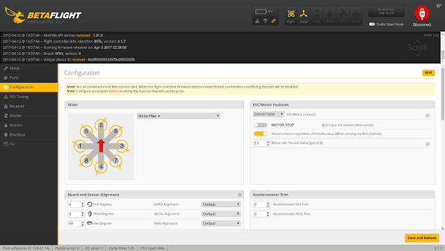
Since Betaflight 3.x.x there is possibility to remap your motor outputs. This allows you to use different pins in case some of them are broken.
There are few tutorials on youtube how to remap your outputs, but I found only one, which takes into account DSHOT.
Problem with remapping with DSHOT is that, not every flight controller output can be used as a DSHOT output.
But how to find which output can be used for DSHOT?
I'm using SPRACINGF3EVO which has 8 motor outputs, so I selected "Octo Flat +"
You should get something as follows, with importrant parts in BOLD.
There are few tutorials on youtube how to remap your outputs, but I found only one, which takes into account DSHOT.
Problem with remapping with DSHOT is that, not every flight controller output can be used as a DSHOT output.
But how to find which output can be used for DSHOT?
First, if you already made some changes to resources in CLI, revert them or re-flash your flight controller.
Depending on your board, select the quadcopter type with same amount of motors as yours.I'm using SPRACINGF3EVO which has 8 motor outputs, so I selected "Octo Flat +"

Go to the CLI and run command "resource" and then "resource list"
Copy and whole output to the notepad
Copy and whole output to the notepad
You should get something as follows, with importrant parts in BOLD.
# resource
resource BEEPER 1 C15
resource MOTOR 1 A00
resource MOTOR 2 A01
resource MOTOR 3 A02
resource MOTOR 4 A03
resource MOTOR 5 A06
resource MOTOR 6 A07
resource MOTOR 7 B00
resource MOTOR 8 B01
resource MOTOR 9 B10
resource MOTOR 10 B11
resource PPM 1 A15
resource LED_STRIP 1 A08
resource SERIAL_TX 1 A09
resource SERIAL_TX 2 A14
resource SERIAL_TX 3 B10
resource SERIAL_RX 1 A10
resource SERIAL_RX 2 A15
resource SERIAL_RX 3 B11

# resource list
IO
A00: MOTOR 1
A01: MOTOR 2
A02: MOTOR 3
A03: MOTOR 4
A04: FREE
A05: FREE
....

DMA:
DMA1 Channel 1: MOTOR 3
DMA1 Channel 2: MOTOR 7
DMA1 Channel 3: MOTOR 8
DMA1 Channel 4: FREE
DMA1 Channel 5: MOTOR 1
DMA1 Channel 6: MOTOR 5
DMA1 Channel 7: MOTOR 2
DMA2 Channel 1: FREE
DMA2 Channel 2: FREE
DMA2 Channel 3: FREE
DMA2 Channel 4: FREE
DMA2 Channel 5: FREE
Last part with the DMA... tells us, which MOTOR outputs can be used for DSHOT.
For my F3 EVO it's motor output 1,2,3,5,7 and 8.
My board had pins 1 and 2 broken, so I had to use 3,5,7 and 8.
Easiest way to map all motors correctly is to first free our DMA capable outputs (3,5,7 and 8).
You can do this with command:
resource MOTOR 3 none
resource MOTOR 3 none
resource MOTOR 5 none
resource MOTOR 7 none
resource MOTOR 8 none
Following image shows default motor numbering for betaflight.
Let's start with MOTOR 1. Check to which pin is this motor soldered to.
If you soldered that motor to ouput number 7, you have to go back to your notepad and look for the first part of the output for the
MOTOR 7 - I know, this is little bit confusing.
For me it was: resource MOTOR 7 B00
In this case we're looking for the last code - B00 which is identifier of the output 7.
To assign this output run cli command
resource MOTOR 1 B00
Repeat this for all 4 motors and then enter save, reboot the board and you're all set!

What actually is this MOTOR all about? Also share the basic introduction of about this, because this is something new to me. Thank you.
ReplyDelete